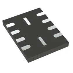
이미지는 참조용입니다.
ACPM-5201-TR1G
+BOMIC AMP UMTS 1.92-1.98GHZ 10SMD
-
제조업체브로드컴 유한회사
-
제조업체 부품 #ACPM-5201-TR1G
-
데이터시트 ACPM-5201-TR1G DataSheet
-
패키지 10-SMD Module
-
재고2000
365 1일 품질 보증
7*24 영업 시간 서비스 보증
90-판매 후 1일 보증
정품 보증
사양
| 속성 | 가치 |
| Supplier | Broadcom Limited |
| Package / Case | Tape & Reel (TR) |
| Part Status | Obsolete |
| Frequency | 1.92GHz ~ 1.98GHz |
| Gain | 27dB |
| RF Type | UMTS |
| Voltage - Supply | 3.2V ~ 4.2V |
| Supply Current | 423mA |
| Test Frequency | 1.92GHz ~ 1.98GHz |
| Mounting Type | Surface Mount |
개요
Description
For a technical document or course, the introduction might outline the scope, objectives, and structure of the material, providing a roadmap for understanding more detailed sections. It could also discuss the significance of the technology or process, historical background, and relevance to current industry practices.
Without additional information about what ACPM-5201-TR1G specifically refers to, this description remains generic. For precise details, consulting the full material or syllabus would be necessary to understand its specific focus and goals.
Equivalent
Features
1. Frequency Range: It operates within a specific frequency range, typically for cellular bands.
2. High Efficiency: It provides efficient power amplification suitable for mobile devices, prolonging battery life.
3. Output Power: The module delivers a high output power, making it suitable for robust communication in various environments.
4. Small Form Factor: It is designed in a compact package, which is ideal for integration into space-constrained devices like smartphones.
5. Low Voltage Operation: The device operates at a low voltage, which is suitable for battery-powered applications.
6. Linear Performance: Offers good linearity, which helps in maintaining signal integrity and reducing distortion.
7. Thermal Management: Built-in features for efficient thermal management to ensure reliable performance over a range of temperatures.
8. Compliance: Designed to meet specific industry standards for wireless communication, ensuring compatibility and reliability.
These features make it a suitable choice for enhancing the performance of wireless communication devices.
Pinout
1. VCC: Supply voltage for the power amplifier.
2. GND: Ground connection.
3. RF IN: Input for the RF signal that needs amplification.
4. RF OUT: Output for the amplified RF signal.
5. Vmode1/Vmode2: Mode control pins for selecting different bias levels or operational modes.
6. VEN: Enable pin to turn the amplifier on or off.
7. Bias: Pin for external biasing.
8. Detector: Provides feedback for power detection.
9. AUX: Auxiliary functions or reserved for future use.
10. NC: Not connected or reserved for internal use.
This configuration ensures efficient amplification of signals for communication systems. Always refer to the manufacturer's datasheet for precise specifications and pin assignments.