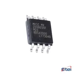
이미지는 참조용입니다.
HMC434E
+BOMIC FREQ DIVIDER DC-8GHZ SOT26
-
제조업체아날로그 디바이스(주)
-
제조업체 부품 #HMC434E
-
데이터시트 HMC434E DataSheet
-
패키지 SOT-23-6
-
재고5902
365 1일 품질 보증
7*24 영업 시간 서비스 보증
90-판매 후 1일 보증
정품 보증
사양
| 속성 | 가치 |
| Package / Case | Strip |
| Part Status | Active |
| Function | Prescaler |
| Frequency | 0Hz ~ 8GHz |
| RF Type | General Purpose |
| Secondary Attributes | Divide by 8 |
| Mounting Type | Surface Mount |
개요
Description
Key features of the HMC434E include its wide tuning range, low phase noise, and high output power. It operates with a supply voltage of typically 5V and offers an output power of around 10 dBm. The VCO is designed to deliver stable frequency performance across its operating temperature range.
The HMC434E is available in a compact, leadless 4x4 mm surface-mount package, which makes it easy to integrate into PCBs for various applications. Its construction and design ensure that it provides a reliable solution for engineers looking to implement high-frequency oscillators in their systems. The VCO is commonly used in military, industrial, and commercial settings where robust performance is required.
Equivalent
Features
1. Frequency Range: Operates typically from 1.5 GHz to 2.0 GHz, making it suitable for a variety of RF applications.
2. Output Power: Offers a typical output power of +8 dBm, ensuring strong signal transmission.
3. Phase Noise: Exhibits low phase noise, typically around -106 dBc/Hz at a 100 kHz offset, which is crucial for maintaining signal integrity in communication systems.
4. Supply Voltage: Operates with a supply voltage range of 3V to 5V, providing flexibility in different system designs.
5. Tuning Voltage: Utilizes a tuning voltage between 0V and 13V to adjust the output frequency.
6. Package: Comes in a compact, leadless 4x4 mm SMT package, facilitating easy integration into circuit boards.
7. Power Consumption: Consumes low power, typically around 28 mA, which is beneficial for battery-powered applications.
The HMC434E is ideal for a variety of applications, including phase-locked loops (PLLs), frequency synthesis, and wireless communication systems.
Pinout
1. Vtune (Pin 1): Voltage tuning input to control the frequency of the VCO.
2. GND (Pins 2, 3, 5, 7): Ground connections for electrical grounding and stability.
3. Vcc (Pin 4): Positive supply voltage input for the VCO.
4. RF OUT (Pin 6): Radio frequency output where the generated signal is delivered.
5. Vreg (Pin 8): Regulated voltage input for biasing the internal circuitry.
This VCO is used in applications such as phase-locked loops, test equipment, and general RF/microwave communications due to its wide frequency range and high output power.