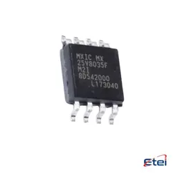
이미지는 참조용입니다.
L6562DTR
+BOMIC PFC CTRLR TRANSITION 1MHZ 8SO
-
제조업체ST마이크로일렉트로닉스(주)
-
제조업체 부품 #L6562DTR
-
데이터시트 L6562DTR DataSheet
-
패키지 SOP-8
-
재고4932
365 1일 품질 보증
7*24 영업 시간 서비스 보증
90-판매 후 1일 보증
정품 보증
사양
| 속성 | 가치 |
| Package / Case | Tape & Reel (TR),Cut Tape (CT) |
| Part Status | Not For New Designs |
| Mode | Discontinuous (Transition) |
| Frequency - Switching | 1MHz |
| Current - Startup | 40 µA |
| Voltage - Supply | 10.3V ~ 22V |
| Operating Temperature | -25°C ~ 125°C |
| Mounting Type | Surface Mount |
개요
Description
Equivalent
1. FAN7527B from ON Semiconductor
2. NCP1653 from ON Semiconductor
3. UCC28019 from Texas Instruments
4. CM6562 from Champion Microelectronic Corp
5. ICE3PCS01G from Infineon Technologies
Each of these provides similar power factor correction functionalities in various applications. Compatibility should still be verified with specific circuit requirements.
Features
1. Transition-Mode Operation: Optimizes switching losses and enhances power efficiency.
2. Wide Range Input Voltage: Supports a broad input voltage range, making it versatile for various applications.
3. Enhanced EMC Performance: Designed to improve Electromagnetic Compatibility, reducing interference with other electronic devices.
4. Low Start-up Current: Minimizes energy consumption during the initial power-up phase.
5. Overvoltage Protection (OVP): Safeguards the system from excessive voltage levels.
6. Undervoltage Lockout (UVLO): Ensures that the device operates only when supply voltage is above a certain threshold.
7. Open-Loop Protection: Provides safety mechanisms to prevent damage in open-loop conditions.
8. Multiplier with THD Optimization: Reduces Total Harmonic Distortion, improving power quality.
9. Soft-Start Capability: Prevents stress on components during power-up, enhancing longevity.
These features make the L6562DTR suitable for use in applications like power adapters, lighting systems, and industrial power supplies.
Pinout
1. INV: Inverting input of the error amplifier.
2. COMP: Output of the error amplifier. A compensation network is connected from this pin to INV for stability.
3. MULT: Input to the multiplier stage, which also receives a signal proportional to the instantaneous AC line voltage.
4. CS: Current sense input. Provides cycle-by-cycle peak current limiting.
5. ZCD: Zero current detection input, used for transition-mode operation.
6. GND: Ground.
7. GD: Gate driver output, used to drive the external MOSFET.
8. VCC: Supply voltage input.
The L6562DTR is widely used in power supply units to improve power factor and reduce harmonics, crucial for meeting international standards for energy efficiency.
Manufacturer
Application
1. Switching Power Supplies: Enhances power factor in power supplies for computers and consumer electronics.
2. LED Drivers: Ensures efficient power conversion and compliance with regulatory standards for LED lighting.
3. Industrial Power Systems: Provides efficient power management in industrial equipment and systems.
4. Home Appliances: Improves energy efficiency in appliances like refrigerators and washing machines.
5. Battery Chargers: Optimizes power delivery and efficiency in battery charging systems.
Its ability to operate in transition mode helps to achieve high efficiency and low electromagnetic interference (EMI).