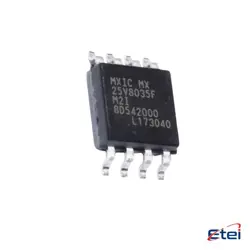
이미지는 참조용입니다.
MAX2373ETC+
+BOMLNA WITH STEP ATTENUATOR AND VGA
-
제조업체아날로그 장비 주식회사/Maxim 통합
-
제조업체 부품 #MAX2373ETC+
-
데이터시트 MAX2373ETC+ DataSheet
-
재고198
365 1일 품질 보증
7*24 영업 시간 서비스 보증
90-판매 후 1일 보증
정품 보증
사양
| 속성 | 가치 |
| Supplier | Rochester Electronics, LLC |
| Package / Case | Bulk |
| Part Status | Active |
개요
Description
Key features of the MAX2373ETC+ include very low noise figure, which minimizes the degradation of the signal-to-noise ratio, and high linearity, which helps maintain the integrity of the GPS signal. The device operates on a single power supply and is designed for low power consumption, making it suitable for portable and battery-operated GPS devices. It also includes shutdown capability to conserve power when the GPS function is not in use.
The MAX2373ETC+ is housed in a compact package, allowing for easy integration into small or space-constrained designs. Its robustness and performance make it suitable for automotive, personal navigation, and timing applications where GPS signal precision and reliability are critical.
Equivalent
Features
1. Low Power Consumption: Optimized for battery-powered devices with minimal power usage in both active and standby modes.
2. Highly Integrated Design: Incorporates essential RF components, reducing the need for external parts and simplifying the design.
3. High Performance: Offers excellent linearity and noise figure, enhancing signal quality and system performance.
4. Wideband Operation: Supports a broad frequency range to accommodate various standards and operational needs.
5. Compact Package: Available in a small package, making it suitable for space-constrained applications.
6. Temperature Range: Operates effectively over a wide temperature range, ensuring reliability in different environments.
These features make the MAX2373ETC+ a suitable choice for modern wireless communication systems requiring efficiency, compactness, and robust performance.
Pinout
1. RF IN: Input for the RF signal that needs to be detected and measured.
2. VCC: Supply voltage pin for powering the device.
3. OUT: Output pin that provides a DC voltage proportional to the RF input power.
4. GND: Ground connection for the circuit.
5. BYP: Bypass pin for connecting an external capacitor to stabilize the internal reference.
6. EN (Enable): Control pin to enable or disable the device.
7. COM: Common pin that may be used for an additional ground or other functions depending on specific configurations.
8. Additional pins could be for specific functionalities like temperature compensation or additional control inputs.
For precise connections and functions, refer to the device's datasheet, as specific pin configurations can vary depending on the package type and application requirements.