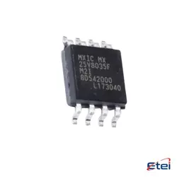
이미지는 참조용입니다.
MAX2641EUT+
+BOMSIGE ULTRA-LOW-NOISE AMPLIFIER
-
제조업체아날로그 장비 주식회사/Maxim 통합
-
제조업체 부품 #MAX2641EUT+
-
데이터시트 MAX2641EUT+ DataSheet
-
패키지 SOT-23-6
-
재고4388
365 1일 품질 보증
7*24 영업 시간 서비스 보증
90-판매 후 1일 보증
정품 보증
사양
| 속성 | 가치 |
| Supplier | Rochester Electronics, LLC |
| Package / Case | Bulk |
| Part Status | Active |
| Frequency | 1.4GHz ~ 2.5GHz |
| P1d B | -21dBm |
| Gain | 14.4dB |
| Noise Figure | 1.3dB |
| RF Type | Cellular, GPS, PCS |
| Voltage - Supply | 2.7V ~ 5.5V |
| Supply Current | 6.4mA |
| Test Frequency | 1.9GHz |
| Mounting Type | Surface Mount |
개요
Description
Equivalent
1. Analog Devices ADL5523 - Offers similar low noise performance suitable for RF applications.
2. Skyworks SKY65050-372LF - Another low-noise amplifier with comparable specifications.
3. Qorvo TQP3M9009 - Provides similar gain and noise figure.
4. Infineon BGA715N7 - Suitable for applications needing low noise amplification.
Always verify specific performance and application requirements before selecting a replacement.
Features
1. Operating Frequency: It supports a frequency range from 50 MHz to 500 MHz, making it versatile for various RF applications.
2. Low Noise Figure: The device offers a noise figure as low as 1.3 dB, enhancing signal sensitivity and performance.
3. High Gain: It provides a typical gain of 15.5 dB, ensuring strong signal amplification.
4. Low Power Consumption: The amplifier operates with a low supply current of about 3.5 mA, making it suitable for battery-powered devices.
5. Supply Voltage: It operates on a single supply voltage ranging from 2.7V to 5.5V.
6. Package: The MAX2641EUT+ is available in a compact 6-pin SOT23 package, facilitating easy integration into circuit designs.
7. Input and Output Matching: It requires minimal external components for input and output impedance matching, simplifying design and reducing costs.
These features make the MAX2641EUT+ ideal for enhancing the performance of RF signal paths in a wide range of applications.
Pinout
1. RF IN (Pin 1): This is the RF input pin where the RF signal is fed into the amplifier.
2. GND (Pin 2): Ground connection for the IC.
3. RF OUT (Pin 3): This is the RF output pin where the amplified RF signal is taken.
4. VCC (Pin 4): Power supply pin for the IC, typically requiring a supply voltage around 2.7V to 5.5V.
5. SHDN (Pin 5): Shutdown pin used to enable or disable the LNA. A logic low will disable the amplifier, reducing power consumption.
6. GND (Pin 6): Another ground connection to further ensure proper grounding and performance.
These pins collectively enable the MAX2641EUT+ to function effectively as a high-performance, low-noise amplifier for RF applications, suitable for enhancing signal strength in various communication devices.