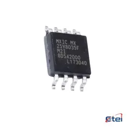
이미지는 참조용입니다.
PMCM6501VPE023
+BOMSMALL SIGNAL FIELD-EFFECT TRANSI
-
제조업체은지포미국주식회사
-
제조업체 부품 #PMCM6501VPE023
-
데이터시트 PMCM6501VPE023 DataSheet
-
재고5141
365 1일 품질 보증
7*24 영업 시간 서비스 보증
90-판매 후 1일 보증
정품 보증
사양
| 속성 | 가치 |
| Package | Bulk |
| ProductStatus | Active |
개요
Description
If PMCM6501VPE023 is indeed a course, the "PMCM" might indicate a focus on project management or a specialized subfield within a broader subject. The numbers could represent a specific sequence or level within a program, indicating its position in the curriculum. The "VPE" might denote a specific department or focus area, such as "Virtual Project Environment" or "Value-Driven Project Execution," for example.
To gain a clearer understanding, consulting the relevant program's syllabus, course catalog, or academic advisor would provide specific details about the objectives, content, and outcomes of PMCM6501VPE023.
Equivalent
Features
1. Dual MOSFET Configuration: Combines both N-channel and P-channel MOSFETs in a single package for compact designs.
2. Low ON-Resistance: Ensures minimal power loss and efficient operation, making it suitable for switching applications.
3. High-Speed Switching: Supports rapid switching speeds, enhancing performance in dynamic applications.
4. Low Voltage Operation: Operates effectively at lower voltages, which is ideal for battery-powered devices.
5. Compact Package: Available in a small, surface-mount package, which saves board space and is compatible with automated assembly processes.
6. Thermal Efficiency: Designed to handle temperature variations effectively, ensuring reliable performance.
7. Wide Applicability: Suitable for use in DC-DC converters, load switches, and power management systems.
These features make the PMCM6501VPE023 a versatile and efficient choice for power management needs in compact, high-performance electronics.
Pinout
The specific pin count for this device is 6 pins. The functions of these pins are generally divided between the two MOSFETs, with connections for the source, gate, and drain of each transistor. Typically, the pin configuration includes:
1. Source (S) of N-channel MOSFET
2. Gate (G) of N-channel MOSFET
3. Drain (D) of N-channel MOSFET
4. Drain (D) of P-channel MOSFET
5. Gate (G) of P-channel MOSFET
6. Source (S) of P-channel MOSFET
These devices are used in various applications for switching and amplifying signals in electronic circuits, providing efficient operation with minimal space requirements.