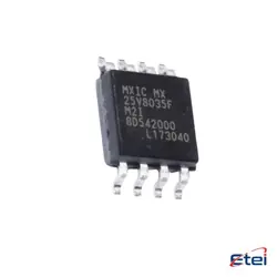
이미지는 참조용입니다.
UC1717SP/883B
+BOMSTEPPER MOTOR DRIVE CIRCUIT, CER
-
제조업체텍사스 인스트루먼트(주)
-
제조업체 부품 #UC1717SP/883B
-
데이터시트 UC1717SP/883B DataSheet
-
재고7856
365 1일 품질 보증
7*24 영업 시간 서비스 보증
90-판매 후 1일 보증
정품 보증
사양
| 속성 | 가치 |
| Package | Bulk |
| ProductStatus | Active |
개요
Description
The "883B" designation indicates compliance with specific military standards, which include rigorous testing for temperature, humidity, shock, and vibration, making the device suitable for demanding environments. The "SP" signifies a specific package type, which impacts how the IC is mounted onto circuit boards and its compatibility with other components.
Overall, the UC1717SP/883B is chosen for applications where reliability, precision, and durability are paramount, such as in avionics, defense systems, or space equipment, where failure is not an option. Its robust design and compliance with military standards ensure consistent performance in critical situations.
Equivalent
Features
1. Wide Supply Voltage Range: It operates effectively over a broad range of supply voltages.
2. High-Speed Operation: The device is optimized for high-frequency switching, making it suitable for fast-paced applications.
3. Short Propagation Delays: It has low propagation delays, enhancing its performance in timing-sensitive circuits.
4. High Output Drive Capability: This feature allows it to drive heavy loads without significant performance degradation.
5. Low Power Consumption: The UC1717SP/883B is designed to consume minimal power, making it efficient for long-term use.
6. Thermal Protection: Built-in thermal protection mechanisms help prevent overheating and potential damage.
7. Military-Grade Reliability: As denoted by the “883B” suffix, it meets stringent military standards for reliability and performance.
These features make the UC1717SP/883B suitable for various demanding applications that require high speed, efficiency, and reliability.
Pinout
The pin functions are typically as follows:
1. VCC: Supply voltage.
2. GND: Ground reference.
3. PWM Input: Pulse Width Modulation input for speed control.
4. Hall Sensor Inputs: Multiple pins for connecting Hall effect sensors which detect motor position.
5. Output Pins: For driving motor phases, commonly three or four pins depending on configuration.
6. Current Sense: Input for monitoring motor current.
7. Enable/Disable: Control pin for turning the motor on or off.
8. Fault Detection: Pin for outputting error status.
9. Thermal Protection: Ensures the device operates within safe temperature limits.
These functions may vary slightly based on the specific manufacturer’s design and application requirements. Always refer to the manufacturer’s datasheet for precise pin configuration and functional details.
Manufacturer
Application
1. Instrumentation: Provides a stable reference for measuring instruments.
2. Data Acquisition Systems: Ensures accuracy in converting analog signals to digital.
3. A/D and D/A Converters: Stabilizes and improves the performance of converters.
4. Precision Regulators: Used in circuits that require precise voltage regulation.
5. Test Equipment: Ensures consistent and reliable operation of test and measurement devices.
6. Calibration Systems: Provides a stable reference for calibrating other devices.
Its robust performance under various conditions makes it suitable for high-reliability applications.