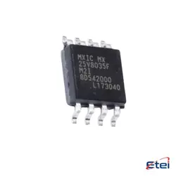
이미지는 참조용입니다.
UPA1901TE-T1-A
+BOMMOSFETs
-
제조업체리사 전자
-
제조업체 부품 #UPA1901TE-T1-A
-
재고22356
365 1일 품질 보증
7*24 영업 시간 서비스 보증
90-판매 후 1일 보증
정품 보증
사양
| 속성 | 가치 |
개요
Description
The UPA1901TE-T1-A is likely a semiconductor component, specifically a transistor or integrated circuit, manufactured by a company specializing in electronic components. In such components, the model number typically indicates specific features, such as the type, configuration, and electrical characteristics like voltage, current, and power ratings.
In general, transistors like this are used for switching or amplification in electronic circuits. The suffix in the model number can denote package type, temperature range, or particular variations in specifications. This component might be used in various applications, including power management, signal processing, or as a part of larger integrated circuits. For precise details, including electrical specifications, typical applications, and pin configurations, one would need to refer to the manufacturer's datasheet. The datasheet is crucial for understanding the component's capabilities, limitations, and best use cases.
In general, transistors like this are used for switching or amplification in electronic circuits. The suffix in the model number can denote package type, temperature range, or particular variations in specifications. This component might be used in various applications, including power management, signal processing, or as a part of larger integrated circuits. For precise details, including electrical specifications, typical applications, and pin configurations, one would need to refer to the manufacturer's datasheet. The datasheet is crucial for understanding the component's capabilities, limitations, and best use cases.
Equivalent
The UPA1901TE-T1-A is a MOSFET transistor used for switching and amplifying electronic signals. Equivalent products may include:
1. NXP BUK9Y29-75B
2. ON Semiconductor NTD5867NL
3. Vishay SI4925DDY
4. STMicroelectronics STP55NF06L
These equivalents share similar specifications, but always verify datasheets to ensure compatibility with your specific application.
1. NXP BUK9Y29-75B
2. ON Semiconductor NTD5867NL
3. Vishay SI4925DDY
4. STMicroelectronics STP55NF06L
These equivalents share similar specifications, but always verify datasheets to ensure compatibility with your specific application.
Features
The UPA1901TE-T1-A is a N-channel MOSFET designed for use in various electronic applications. Its key features include:
1. Low On-Resistance: This component exhibits a low on-resistance, which helps improve efficiency by reducing energy loss during conduction.
2. High-Speed Switching: It is capable of fast switching times, making it suitable for applications requiring quick response.
3. Drain-Source Voltage (Vds): It typically supports a high drain-source voltage, allowing it to handle relatively high power.
4. Drain Current (Id): The MOSFET can manage a substantial drain current, which is beneficial for high-power applications.
5. Small Package Size: The component often comes in a compact package, making it ideal for applications where space is limited.
6. Enhanced Thermal Performance: It is designed to dissipate heat efficiently, which extends its operational lifespan and reliability.
7. Applications: It is commonly used in power management, DC-DC converters, motor control, and other applications needing efficient switching.
These features make the UPA1901TE-T1-A a versatile choice for engineers and designers looking for efficient and reliable MOSFETs in their electronic projects.
1. Low On-Resistance: This component exhibits a low on-resistance, which helps improve efficiency by reducing energy loss during conduction.
2. High-Speed Switching: It is capable of fast switching times, making it suitable for applications requiring quick response.
3. Drain-Source Voltage (Vds): It typically supports a high drain-source voltage, allowing it to handle relatively high power.
4. Drain Current (Id): The MOSFET can manage a substantial drain current, which is beneficial for high-power applications.
5. Small Package Size: The component often comes in a compact package, making it ideal for applications where space is limited.
6. Enhanced Thermal Performance: It is designed to dissipate heat efficiently, which extends its operational lifespan and reliability.
7. Applications: It is commonly used in power management, DC-DC converters, motor control, and other applications needing efficient switching.
These features make the UPA1901TE-T1-A a versatile choice for engineers and designers looking for efficient and reliable MOSFETs in their electronic projects.
Pinout
The UPA1901TE-T1-A is a MOSFET transistor produced by Renesas Electronics. It is typically used for switch-mode power supplies and load switch applications. This component comes in an 8-pin package. The pin configuration is as follows:
1. Source (S1)
2. Gate (G1)
3. Drain (D1) - internally connected to the tab
4. Source (S1)
5. Source (S2)
6. Gate (G2)
7. Drain (D2) - internally connected to the tab
8. Source (S2)
Each MOSFET within the package has its own gate and source, while the drains are commonly connected internally. This dual N-channel MOSFET configuration is designed for high-speed switching with low on-resistance, making it suitable for efficient power management in various electronic devices.
1. Source (S1)
2. Gate (G1)
3. Drain (D1) - internally connected to the tab
4. Source (S1)
5. Source (S2)
6. Gate (G2)
7. Drain (D2) - internally connected to the tab
8. Source (S2)
Each MOSFET within the package has its own gate and source, while the drains are commonly connected internally. This dual N-channel MOSFET configuration is designed for high-speed switching with low on-resistance, making it suitable for efficient power management in various electronic devices.
Manufacturer
The UPA1901TE-T1-A is manufactured by Renesas Electronics Corporation. Renesas is a global semiconductor company that specializes in the design and manufacture of microcontrollers, analog, power, and system-on-chip (SoC) products. It serves a wide range of industries, including automotive, industrial, home electronics, and information communication technology (ICT). Renesas is known for providing comprehensive solutions that integrate both hardware and software to improve the performance and efficiency of electronic systems.
Application
The UPA1901TE-T1-A is a small signal MOSFET commonly used in electronic applications that require switching and amplification. Typical application areas include power management circuits, load switches, and DC-DC converters in various consumer electronics, such as smartphones, tablets, and laptops. It is also utilized in automotive electronics for energy-efficient power distribution and in industrial systems for controlling small motors or actuators. Its compact size and low on-resistance make it suitable for space-constrained and battery-operated devices where efficient power management is crucial.
Package
The UPA1901TE-T1-A is a surface-mount device (SMD) package, specifically a small outline transistor (SOT-323) package. This compact package is designed for high-density mounting on circuit boards, making it ideal for applications where space is a constraint.