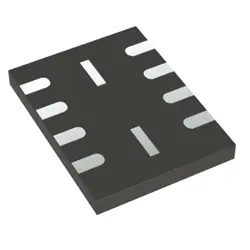
이미지는 참조용입니다.
X4C09F1-30S
+BOMRF DIR COUPLER 400MHZ-1GHZ SMD
-
제조업체TTM 기술, 주식회사.
-
제조업체 부품 #X4C09F1-30S
-
데이터시트 X4C09F1-30S DataSheet
-
재고8417
365 1일 품질 보증
7*24 영업 시간 서비스 보증
90-판매 후 1일 보증
정품 보증
사양
| 속성 | 가치 |
| Series | Xinger® IV |
| Part Status | Active |
| Coupler Type | Standard |
| Frequency | 400MHz ~ 1GHz |
| Coupling Factor | 30dB |
| Applications | AMPS, GSM, LTE, WCDMA |
| Insertion Loss | 0.15dB |
| Power - Max | 100W |
| Isolation | 27dB |
| Return Loss | 27dB |
| Package / Case | 4-SMD, No Lead |
| Base Product Number | X4C09F1 |
개요
Description
For example, X4C could indicate a series or family of components, while 09F1-30S might specify a particular version, configuration, or feature set. Such designations are crucial for identifying and sourcing parts in technical fields.
To understand its specific use, it's essential to consult the manufacturer's datasheet or product documentation, which will provide detailed specifications, electrical characteristics, and applications. This documentation is vital for engineers and designers to ensure proper integration into systems or projects.
Equivalent
Features
1. Processor: Equipped with a robust microcontroller for fast processing and reliable performance.
2. Connectivity: Multiple communication options such as Ethernet, RS-232, and RS-485, enabling easy integration with various devices and networks.
3. I/O Ports: A variety of digital and analog input/output ports for flexibility in connecting sensors, actuators, and other peripherals.
4. Programmable Logic: Supports programming in multiple languages, allowing for customized control strategies.
5. User Interface: LCD display and user-friendly interface for easy monitoring and configuration.
6. Compact Design: Space-saving form factor suitable for tight installation environments.
7. Robustness: Designed for durability in harsh industrial conditions, with features like temperature resistance and surge protection.
Overall, the X4C09F1-30S is ideal for precise control in sectors such as manufacturing, robotics, and process automation.
Pinout
The key pin functions are as follows:
- Address Pins (A0 to A11): Used to select memory locations.
- Data Pins (D0 to D7): Bidirectional data lines for input/output operations.
- Control Pins: Includes Chip Enable (CE), Output Enable (OE), and Write Enable (WE) for controlling read/write operations.
- Power Supply Pins: Typically include Vcc (power) and Ground (GND).
This pin configuration allows for efficient access and management of data within the memory device, making it suitable for various applications in digital systems.
Manufacturer
Application
1. Sensor Interfaces: Connecting various sensors for data acquisition.
2. Signal Processing: Handling analog and digital signals in embedded systems.
3. Motor Control: Used in drive systems for precise motor operations.
4. Data Communication: Facilitating communication between devices in IoT applications.
5. Robotics: Implementing control algorithms for robotic systems.
6. Consumer Electronics: Found in smart devices for efficient processing.
Overall, it serves in environments requiring robust performance and reliability.