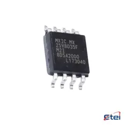
이미지는 참조용입니다.
DMP4025LSD-13
+BOMMOSFET 2P-CH 40V 6.9A 8SO
-
제조업체다이오즈(주)
-
제조업체 부품 #DMP4025LSD-13
-
재고9479
365 1일 품질 보증
7*24 영업 시간 서비스 보증
90-판매 후 1일 보증
정품 보증
사양
| 속성 | 가치 |
| Part Status | Active |
| Technology | MOSFET (Metal Oxide) |
| Configuration | 2 P-Channel (Dual) |
| FET Feature | Logic Level Gate |
| Drain to Source Voltage (Vdss) | 40V |
| Current - Continuous Drain (Id) @ 25°C | 6.9A |
| Rds On (Max) @ Id, Vgs | 25mOhm @ 3A, 10V |
| Vgs(th) (Max) @ Id | 1.8V @ 250µA |
| Gate Charge (Qg) (Max) @ Vgs | 33.7nC @ 10V |
| Input Capacitance (Ciss) (Max) @ Vds | 1640pF @ 20V |
| Power - Max | 1.8W |
| Operating Temperature | -55°C ~ 150°C (TJ) |
| Mounting Type | Surface Mount |
| Package / Case | 8-SOIC (0.154", 3.90mm Width) |
| Supplier Device Package | 8-SO |
| Base Product Number | DMP4025 |
개요
Description
The DMP4025LSD-13 is a N-channel MOSFET designed for power management applications. With a maximum voltage rating of 25V and a continuous drain current up to 40A, it is suitable for high-efficiency switching. The device features a low on-resistance (R_DS(on)) of approximately 10 mΩ, which minimizes power loss and enhances thermal performance.
It operates effectively at high frequencies, making it ideal for applications such as DC-DC converters, power supplies, and motor control systems. The DMP4025LSD-13 comes in a compact surface-mount package, facilitating space-saving on PCBs.
Its robust design ensures reliable operation in various environments, and its low gate charge enables faster switching speeds. Overall, the DMP4025LSD-13 is a versatile choice for engineers seeking efficient and high-performance power solutions in their designs.
It operates effectively at high frequencies, making it ideal for applications such as DC-DC converters, power supplies, and motor control systems. The DMP4025LSD-13 comes in a compact surface-mount package, facilitating space-saving on PCBs.
Its robust design ensures reliable operation in various environments, and its low gate charge enables faster switching speeds. Overall, the DMP4025LSD-13 is a versatile choice for engineers seeking efficient and high-performance power solutions in their designs.
Equivalent
Equivalent products to the DMP4025LSD-13 chip include the DMP4025LSD-13TR, DMP4010LSD-13, and other similar N-channel MOSFETs with comparable specifications. It's essential to check datasheets for precise ratings, including voltage, current, and thermal performance, to ensure compatibility in your application. Additionally, consult with distributors or manufacturers for the latest alternatives.
Features
The DMP4025LSD-13 is an N-channel MOSFET designed for high-efficiency power management applications. Key features include:
1. Voltage Rating: It has a maximum drain-source voltage (V_DS) of 25V, making it suitable for low-voltage applications.
2. Current Rating: The device can handle continuous drain currents up to 40A, allowing it to support high-load scenarios.
3. R_DS(on): It offers a low on-resistance (R_DS(on)) of around 10 mΩ at V_GS = 10V, which minimizes power loss and improves efficiency.
4. Gate Threshold Voltage: The gate-to-source threshold voltage (V_GS(th)) ranges from 1V to 3V, ensuring compatibility with low-voltage gate drive signals.
5. Package: Available in a compact DPAK package, it facilitates efficient thermal management and space-saving designs.
6. Applications: Commonly used in power supplies, DC-DC converters, and motor control applications.
These features make the DMP4025LSD-13 an effective choice for various electronic designs requiring reliable switching performance.
1. Voltage Rating: It has a maximum drain-source voltage (V_DS) of 25V, making it suitable for low-voltage applications.
2. Current Rating: The device can handle continuous drain currents up to 40A, allowing it to support high-load scenarios.
3. R_DS(on): It offers a low on-resistance (R_DS(on)) of around 10 mΩ at V_GS = 10V, which minimizes power loss and improves efficiency.
4. Gate Threshold Voltage: The gate-to-source threshold voltage (V_GS(th)) ranges from 1V to 3V, ensuring compatibility with low-voltage gate drive signals.
5. Package: Available in a compact DPAK package, it facilitates efficient thermal management and space-saving designs.
6. Applications: Commonly used in power supplies, DC-DC converters, and motor control applications.
These features make the DMP4025LSD-13 an effective choice for various electronic designs requiring reliable switching performance.
Pinout
The DMP4025LSD-13 is a dual N-channel MOSFET with a total of 8 pins. The pin configuration and their functions are as follows:
1. Gate 1 (G1) - Controls the first N-channel MOSFET.
2. Drain 1 (D1) - The drain terminal for the first N-channel MOSFET.
3. Source 1 (S1) - The source terminal for the first N-channel MOSFET.
4. Gate 2 (G2) - Controls the second N-channel MOSFET.
5. Drain 2 (D2) - The drain terminal for the second N-channel MOSFET.
6. Source 2 (S2) - The source terminal for the second N-channel MOSFET.
7. Common Source (CS) - Connects both source terminals.
8. Tab (Heat Sink) - Used for thermal management, typically connected to the ground or a heat sink.
This device is commonly used in power management applications due to its low on-resistance and high-speed switching capabilities.
1. Gate 1 (G1) - Controls the first N-channel MOSFET.
2. Drain 1 (D1) - The drain terminal for the first N-channel MOSFET.
3. Source 1 (S1) - The source terminal for the first N-channel MOSFET.
4. Gate 2 (G2) - Controls the second N-channel MOSFET.
5. Drain 2 (D2) - The drain terminal for the second N-channel MOSFET.
6. Source 2 (S2) - The source terminal for the second N-channel MOSFET.
7. Common Source (CS) - Connects both source terminals.
8. Tab (Heat Sink) - Used for thermal management, typically connected to the ground or a heat sink.
This device is commonly used in power management applications due to its low on-resistance and high-speed switching capabilities.
Manufacturer
The DMP4025LSD-13 is manufactured by Diodes Incorporated, a global manufacturer of discrete, analog, and mixed-signal semiconductor solutions. Founded in 1959 and headquartered in Plano, Texas, Diodes Incorporated focuses on providing high-quality, cost-effective semiconductor products for a wide range of applications, including consumer electronics, automotive systems, industrial equipment, and communications. The company is known for its commitment to innovation and reliability, producing a variety of components such as diodes, transistors, and voltage regulators. Diodes Incorporated emphasizes customer service and technical support, catering to the growing demands of the electronic components market. Their products are widely used in both through-hole and surface mount technologies, making them a key player in the semiconductor industry.
Application
The DMP4025LSD-13 is a N-channel MOSFET commonly used in various applications, including power management, DC-DC converters, and switching power supplies. It is suitable for battery management systems, motor control, and load switching due to its low on-resistance and high efficiency. Additionally, it can be found in consumer electronics, automotive systems, and renewable energy applications like solar inverters. Its ability to handle high currents and voltages makes it ideal for both low-voltage and high-voltage applications.
Package
The DMP4025LSD-13 is packaged in a TO-220 type package. This package type is designed for efficient heat dissipation and is commonly used for power devices in various applications.