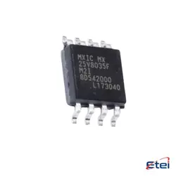
이미지는 참조용입니다.
TD350ETR
+BOMIC GATE DRVR HIGH-SIDE 14SO
-
제조업체ST마이크로일렉트로닉스(주)
-
제조업체 부품 #TD350ETR
-
데이터시트 TD350ETR DataSheet
-
패키지 SOIC-14
-
재고4083
365 1일 품질 보증
7*24 영업 시간 서비스 보증
90-판매 후 1일 보증
정품 보증
사양
| 속성 | 가치 |
| Package / Case | Tape & Reel (TR),Cut Tape (CT) |
| Part Status | Active |
| Driven Configuration | High-Side |
| Channel Type | Single |
| Number of Drivers | 1 |
| Gate Type | IGBT, N-Channel MOSFET |
| Voltage - Supply | 12V ~ 26V |
| Logic Voltage - VILVIH | 0.8V, 4.2V |
| Current - Peak Output(Source Sink) | 1.5A, 2.3A |
| Input Type | Non-Inverting |
| Rise / Fall Time(Typ) | 130ns, 75ns (Max) |
| Operating Temperature | -40°C ~ 150°C (TJ) |
| Mounting Type | Surface Mount |
개요
Description
Key features of the TD350ETR include adjustable time settings, high reliability, and easy integration into existing systems. It often supports multiple timing modes, such as delay-on-operate, delay-on-release, and interval timing, allowing flexibility in different applications. The device is built to withstand industrial environments, with robust housing and protection against electrical noise and interference.
Installation and setup are straightforward, with user-friendly interfaces that might include digital displays or dial settings. The relay is an essential component in enhancing operational efficiency and safety by automating processes and reducing manual interventions. Its compact design allows for easy mounting in control panels, making it a versatile tool for professionals in the automation and electrical engineering sectors.
Equivalent
1. IRS2110 from Infineon Technologies, which offers similar functionality for driving IGBTs.
2. FAN7390 from ON Semiconductor, another close alternative for gate driving applications.
3. UCC21710 from Texas Instruments, which provides comparable performance in IGBT driving tasks.
Always verify specifications and compatibility with your specific application requirements before selecting an equivalent product.
Features
1. Desaturation Protection: The IC provides built-in desaturation protection to prevent damage to the power transistor during fault conditions.
2. Miller Clamping: It includes a Miller clamp to prevent unintended gate turn-on by clamping the gate voltage during high dV/dt events.
3. Soft Turn-off: Ensures controlled shutdown of the power device during fault conditions to minimize stress on the system.
4. Undervoltage Lockout (UVLO): Protects the power transistor by disabling the gate drive if supply voltage drops below a certain threshold.
5. Complementary Outputs: Offers high-side and low-side complementary outputs for effective driving of the power transistors.
6. Wide Temperature Range: Designed to operate reliably over a broad temperature range, making it suitable for demanding environments.
7. Compact Package: Available in a small form factor, facilitating easy integration into various circuit designs.
These features make the TD350ETR suitable for a range of industrial and automotive applications requiring robust and efficient power management.
Pinout
1. VCC (Pin 1): Supply voltage for the gate driver.
2. GND (Pin 2): Ground connection.
3. IN (Pin 3): Input for the control signal, typically from a microcontroller or PWM controller.
4. EN (Pin 4): Enable input; allows the driver to be activated or deactivated.
5. FAULT (Pin 5): Fault status output to indicate fault conditions.
6. DESAT (Pin 6): Desaturation detection input for IGBT protection.
7. OUT (Pins 7 and 8): Outputs to drive the gate of the power transistor.
8. VREG (Pin 9): Regulated voltage output.
9. CLAMP (Pin 10): Gate clamp voltage reference.
10. VEE (Pins 11 and 12): Negative supply voltage.
11. NC (Pins 13 and 14): No connection, reserved for future use or additional functions.
12. RTHRESH (Pin 15): Threshold resistor setting for fault detection.
13. NC (Pin 16): No connection.
These pins collectively facilitate robust gate control, fault protection, and efficient power device management.